Please do not comment here, I am not monitoring the comments. Go to reddit https://www.reddit.com/r/Artillery3D/ or contact me there https://www.reddit.com/user/eazrael/
Nope, got shadowbanned…
I also stopped using the printer.
(stupid German laws keep me off using a real comment software with notifications)
¶ Issues
- Noisy Fans
- Extruder fan is a screamer
- Part fan seems to have some vibration issues due to wind tunnel layout
- PSU fan rattling/squealing on power up, whistling after. Fan is losing lubricant.
Solved after loosening & tighthening the screws holding the PSU fan.
- Distance between z-probe and nozzle too large
- Noisy driver/steppers
- Heavy vibrations
- GPL/LGPL violation in Marlin FW and Cura
- The mysterious black (other's said it's blue) cable from the bed. If the bed heats and the temperature readings are reasonable, just cut it. It's not connected in the base.
- Currently, the extruder is very noisy, maybe I damaged something while tearing the machine down.
Either it's gone or I got used to it.Nope, it's still there The extruder randomly stops at some point during print @300mm/s, maybe I damaged something while tearing the machine down, or need to tighten the grip.Loose/woobly bed.Solved after loosening and tighthening the screws in the print bed- The nozzle clean pushes the back right corner down. Not sure if that is an issue on the long run
Printer bed to low for Autoleveling. Loose all six leveling screws almost until there is no resistance. Start tighening again.
¶ Notes
- USB-C, but 2.0 Full-Speed = 12Mpbs
- “Display-Computer” connected via UART.
- Steppers no more on their own modules
- PCB much denser populated than the X2 Ruby Board, more components
¶ Comparison X2 / X3 Plus
Subjective and not fair
| What | X2 | X3 Plus |
|---|---|---|
| Extruder Heater | Slower | Faster |
| Bed Heater |
|
|
| Loudness | Almost silent | Very noisy |
| Vibrations | Less | Very heavy vibrations and device shakes (no input shaping configured) |
| Print bed | Good joke (coated glass bed) | Really good :-) (metal PEI sheet) |
| Build quality | Rather good | Better |
| Supplied Accessories | Good set | Even more tools and stuff :-) |
¶ Mod: Integrated Print server (X3 Plus)
Will probably never finish this. Ask me if your are interested in anything.
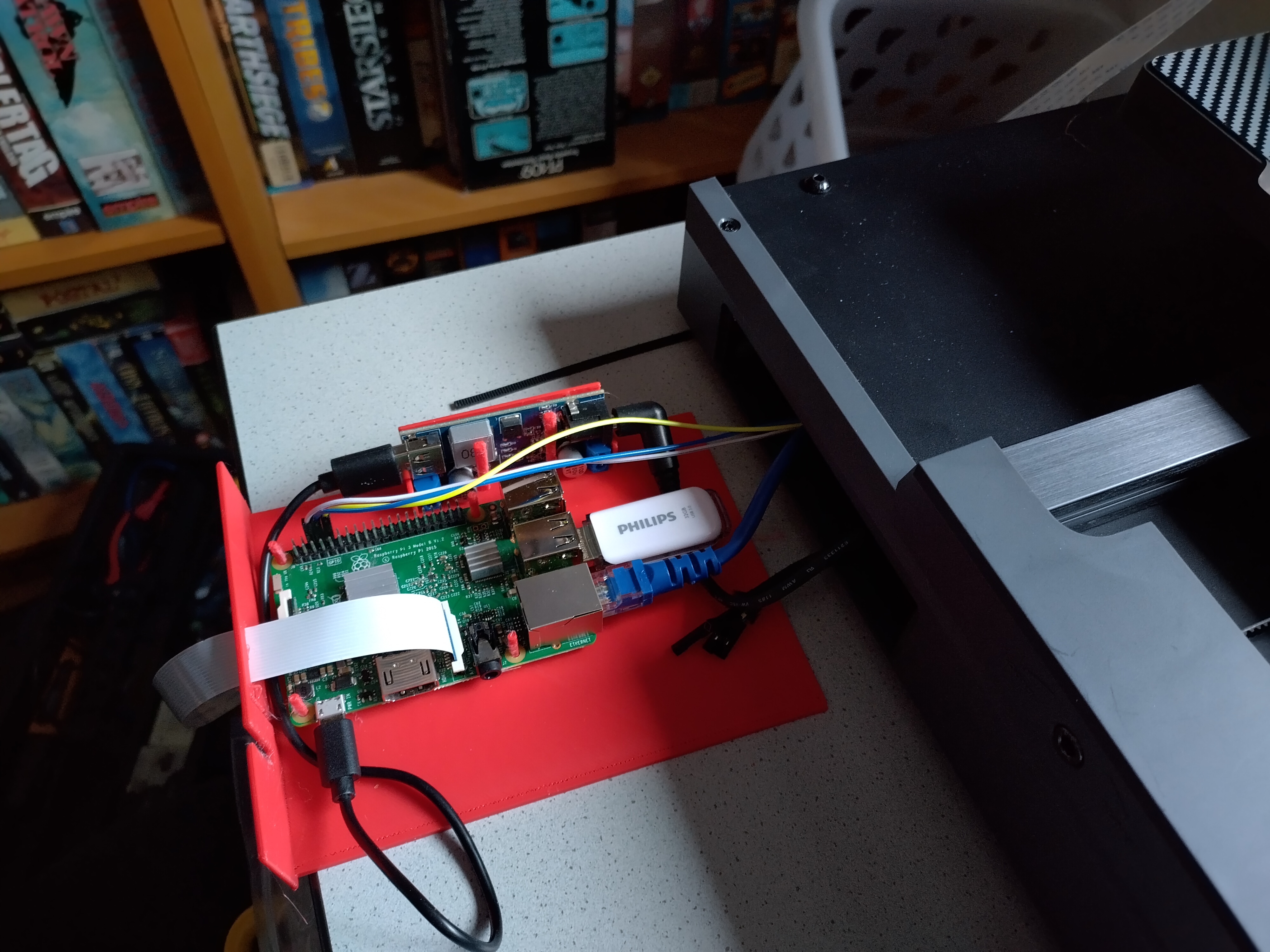
The cam FFC cable now also goes internal to the back instead of the front. The slots were meant for USB+HDMI for a touch screen. Powered via cheap Step-down converter from the free power header on the top right corner of the printer mainboard. LAN goes back and exits via the Y-Stepper Gap. Raspi GPIO connected to internal UART of the printer mainboard where the display was plugged in.No external USB needed.
Sources:
- Tray: https://cad.onshape.com/documents/0a5ec170e96bfcea5ff27e72/w/b02d3950dfb133282c1369db/e/05a353293f138f44fc132e9a
- X-Stepper Camera mount
- https://cad.onshape.com/documents/316c498e2f5919ac9283b0b1/w/ac31a112d4c55cff3f521d7d/e/2bcf0e3fee83516103e95ecc
- https://cad.onshape.com/documents/48bce59d13b0baafb553837a/w/4ce9b6b7b76ba6daa9057ea5/e/169e3a49e4c2ce66415a4a86
- https://cad.onshape.com/documents/6d7689a27302f479a3249828/w/2ead7648047c62658bc5611f/e/ac323193422ee6f1623ecd89
- https://cad.onshape.com/documents/e161c4c0bf8923c0664ef9a7/w/e02cdaae0d2b3bcd7f3ad4cd/e/202274fb805f51ddfd94acb6
Goal: Stash a Raspberry Pi as print server in the drawer of the X3 plus with as few external wires as possibie and (almost) without damaging/destroying anything.
There are few options:
- You can use the internal connector for the printer's display and avoid needing an external USB cable
- You can siphon off power from the unused 24V connector conveniently placed next to the drawer, avoiding an external power line
- You lay an ethernet cable internally to the back side, so there won't be another cable on the front
- HDMI & USB cables for an external touchscreen laid to the back of the printer (I did not do this)
- I am using Klipper/Mainsail, but Marlin/Octoprint should also be possible
Required stuff depending on the chosen options:
- Raspberry Pi
- Three jumper wires
- Filament to print a new tray for the drawer
- Ethernet LAN cable (sorry, no WiFi in a metal box) , probably with a good shielding (no flat U/UTP cables or so)
- Step-Down-Converter from 24V to 5 Volt + cables, I got a cheap ~3€ one
- STLink V2 (clone) adapter + cables (~5€)
- RJ45 Ethernet coupling (for joining two cables)
¶ Instructions
Warning: You do this on your own risk. Don't do anything you aren't confident in and don't do anything unless you understand the why and how.
INCOMPLETE!!!! DON'T DO THIS
Pictures coming soon
The instructions assume that the printer base has been opened and is laying top down and you are look from above.
- Open the base of the printer. You need to break the “warranty void” seal, some Youtube videos suggest you can cheat around destryoing the seal.
- If you want to use the internal connection to the printer, you need to unplug the TFT cable. It's the black 4 ribbon cable coming from the left and going down to the front of the printer. To unplug the connector you need to remove the hot glue. I used Isopropanol alcohol with Q-Tips and tweezer to gently pull out the hot glue softened up by the IPA. After unplugging the connector, there are four pins from the left to the right: (+5V, GND, TX, RX). You need to connect GND, TX, RX to your Raspberry Pi, RX and TX must be crossed. Read the Raspberry Pi documentation to see how they are counted. Make sure your jumper wires or self-made connector is sitting tight on both device.
You need to make configuration changes:- RasPi UART TODO raspi-config
- Octoprint: TODO
- If you want to use Klipper and the internal connection, you have to flash a new firmware to the printer. Run make menuconfig and in the menu select Communication interface and choose USART1 on PA10/PA9. Flash the software via USB to the printer. It's probably a good idea to do this after reassembling the printer In Mainsail, edit your printer.cfg and
Warning: Without a STLink V2 adapter you cannot reflash new firmware onto the microcontroller after you flashed the changed communication interface.
| X3 Connector | RPI GPIO Pin | RPI Header Column | RPI Header Row |
|---|---|---|---|
| GND | GND | 2 | 3 |
| TX | GPIO15 (RX) | 2 | 4 |
| RX | GPIO14 (TX) | 2 | 5 |
- If you want to power the RasPi from the printer, there is an unused 24V socket on the top right corner, left is plus and right is minus/ground. Connect these to your step-down converter. In my tests both the printer and the RasPi 3B ran fine. The RasPi can be powered from the GPIO header, but I prefered a standard USB cable.
- If you want to a LAN connection in the back, lay one ethernet cable from the drawer to the large gap of the Y/bed stepper on the back of the printer where stepper cable goes into the stepper motor. You can comfortably run standard ethernet cables with a good shielding through this. I used also a good shielded cable as i do not know if these steppers emit a lot of electromagnetic noise.
- HDMI/USB for a standard touchscreen may also be routed this way, but personally I prefer this on the front. I did not run a CSI web cam cable through this due to length and the fear of the EMI of the stepper.
- If you want to use Klipper and the internal connection, you have to flash a new firmware to the printer. Run make menuconfig and in the menu select Communication interface and choose USART1 on PA10/PA9. Flash the software via USB to the printer. It's probably a good idea to do this after reassembling the printer In Mainsail, edit your printer.cfg and
Warning: Without a STLink V2 adapter you cannot reflash new firmware onto the microcontroller after changing the communication interface.
¶ Hardware
¶ Components
| Part | Model | Description | Links | Replacements | Pictures |
|---|---|---|---|---|---|
| Bed Heater | |||||
| Bed Thermistor | |||||
| Driver | ADT5833 |
|
Description | ||
| Extruder Thermistor | |||||
| Extruder Fan | UitraFan XD2510D24H | 24 Volt , 0.1A, 3.0 CFM, 8.1mmH2O, 30dBA | Product Page |
WINSINN 2510 (0.04A, 2.2 CFM 22.5dBA) Pengda Tech 25x25x10@24V |
|
| LED Strip | Brightness controllable via PWM | ||||
| Mainboard Fan | UitraFan XD4020D24M | Product Page | |||
| Microcontroller | STM32F402 |
|
STM32F402 Product Page (Datasheet link at bottom) STM32F401 Product Page (Datasheets + manuals) |
||
| Neopixel | |||||
| Part Fan | Product Page | ||||
| Power Supply | YT-450-3624 | ||||
| PSU Fan | FXDS - ??? | 50x50x12 24V Fan, 2 wire voltage controlled (not sure if there is a controller…) | |||
| Stepper Motors |
42SDHC (Axes) 42SDHB (Extruder) |
|
Unreachable: Incomplete model number breakdown Backup: |
||
| Touchscreen Assembly | Nextion/TJC manufactured |
|
Discussion at Unofficial Nextion | ||
| Z-Probe | Baolsen N3F-H4NB |
¶ MCU Pins
| Pin # | Name | Interesting | Description |
| 1 | VBAT | No | Supply Pin |
| 2 | PC13 | ? | ? |
| 3 | PC14-OSC32_In | Yes | Z+. Connected to Z-Probe Probe pin, which has no cable attached. |
| 4 | PC15-OSC32_OUT | ? | ? |
| 5 | PH0-OSC_IN | No | Oscillator |
| 6 | PH1-OSC_OUT | No | Oscillator |
| 7 | NRST | No | Reset + Debug Header 6 |
| 8 | PC0 | Yes | Temperature sensor heat bed |
| 9 | PC1 | Yes | Filament sensor at gantry top & in print head (not populated) |
| 10 | PC2 | Yes | LED Strip |
| 11 | PC3 | ? | ? |
| 12 | VSSA/(VREF- | No | Supply Pin |
| 13 | VDDA/VREF+ | No | Supply Pin |
| 14 | PA0 | No | WIFI Header IO0 |
| 15 | PA1 | No | WIFI Header IO2 |
| 16 | PA2 | No | WIFI Header TXD2 |
| 17 | PA3 | No | WiFI Header RXD2 |
| 18 | VSS | No | Supply Pin |
| 19 | VDD | No | Supply Pin |
| 20 | PA4 | Yes | Driver 4 Pin 3 (Z-Axis direction, positive when low) |
| 21 | PA5 | ? | ? |
| 22 | PA6 | Yes | Extruder Heater |
| 23 | PA7 | Yes | Bed Heater |
| 24 | PC4 | Yes | Driver 4 Pin 1 (Z-Axis enable when low) |
| 25 | PC5 | Yes | Extruder temperature sensor (NTC) |
| 26 | PB0 | Yes | Print head part fan |
| 27 | PB1 | Yes | Print head extruder fan |
| 28 | PB2 | ? | ? |
| 29 | PB10 | Yes | Driver 4 Pin 2 (Z-Axis step) |
| 30 | VCAP_1 | No | Supply Pin |
| 31 | VSS | No | Supply Pin |
| 32 | VDD | No | Supply Pin |
| 33 | PB12 | ? | ? |
| 34 | PB13 | ? | ? |
| 35 | PB14 | ? | ? |
| 36 | PB15 | ? | ? |
| 37 | PC6 | Yes | Driver 3 Pin 3 (Y-Axis/bed direction, positive when low) |
| 38 | PC7 | Yes | Driver 3 Pin 2 (Y-Axis/bed step) |
| 39 | PC8 | Yes | Driver 3 Pin 1 (Y-Axis/bed enable when low) |
| 40 | PC9 | Yes | Driver 2 Pin 3 (X-Axis direction, positive when high) |
| 41 | PA8 | Yes | Driver 2 Pin 2 (X-Axis step) |
| 42 | PA9 | Yes | AUX1 RX1 (Touchscreen via UART) |
| 43 | PA10 | Yes | AUX 1 TX1 (Touchscreen via UART) |
| 44 | PA11 | Yes | USB TX/RX |
| 45 | PA12 | Yes | USB TX/RX |
| 46 | PA13 | No | JTMS-SWDIO Debug Header 1 |
| 47 | VSS | No | Supply Pin |
| 48 | VDD | No | Supply Pin |
| 49 | PA14 | No | JTCK-SWCLK Debug Header 3 |
| 50 | PA15 | Yes | Driver 2 Pin 1 (X-Axis enable when low) |
| 51 | PC10 | Yes | Driver 1 Pin 3 (Extruder direction, extrude when low) |
| 52 | PC11 | Yes | Driver 1 Pin 2 (Extruder step) |
| 53 | PC12 | Yes | Driver 1 Pin 1 (Extruder enable when low) |
| 54 | PD2 | Yes | Print head neopixel |
| 55 | PB3 | Yes | Print head Z-Probe |
| 56 | PB4 | ? | ? Main Power? |
| 57 | PB5 | ? | ? Cap Power? |
| 58 | PB6 | No | ? EEPROM SDA/SCL? |
| 59 | PB7 | No | ? EEPROM SDA/SCL? |
| 60 | BOOT0 | No | Boot0 + Debug Header 2 |
| 61 | PB8 | Yes | Y-Stop |
| 62 | PB9 | Yes | X-Stop |
| 63 | VSS | No | Supply Pin |
| 64 | VDD | No | Supply Pin |
¶ Ribbon Cable Pins
Unfortunately I do not remember if i counted the rows right. With a multi meter, just check if the fifth column is connected to ground.
| Row | Pin | Description | Breakout Board | STM32 Pin |
|---|---|---|---|---|
| 1 | 1 | Z-Stop | Z+ | PC14 |
| 1 | 2 | X-Stop | X- | PB9 |
| 1 | 3 | 2nd Diode | Servo | PB3 |
| 1 | 4 | Diode 2nd left of Fan 1 PC5 → | TH+ | PC5 |
| 1 | 5 | Ground | TH- | |
| 1 | 6 | Ground | Ground | - |
| 1 | 7 | MOSFET | HE0 | PA6 |
| 1 | 8 | MOSFET | HE0 | PA6 |
| 1 | 9 | 24 Volt | 24 Volt | - |
| 1 | 10 | Extruder 2A | Extruder 2A | - |
| 1 | 11 | Extruder 1B | Extruder 1B | - |
| 1 | 12 | X-Stepper 2A | X 2A | - |
| 1 | 13 | X-Stepper 1B | X 2B | - |
| 2 | 1 | 5 Volt | 5 Volt | - |
| 2 | 2 | 5 Volt | - | |
| 2 | 3 | LED | LED | PD2 |
| 2 | 4 | STM32F401 PC1 → | MT | PC1 |
| 2 | 5 | Fan1 | PB1 | |
| 2 | 6 | Fan0 | PB0 | |
| 2 | 7 | MOSFET | HEO | PA6 |
| 2 | 8 | 24 Volt | 24 Volt | - |
| 2 | 9 | 24 Volt | 24 Volt | - |
| 2 | 10 | Extruder 2B | Extruder 2B | - |
| 2 | 11 | Extruder 1A | Extruder 1A | - |
| 2 | 12 | X Stepper 2B | X 2B | - |
| 2 | 13 | X Stepper 1A | X 1A | - |
¶ Software
¶ Cura
¶ G-Codes from Artillery Cura
X3 Plus Start Code
G12 C2
G92 E0 ; reset extruder
G28 Z
G1 Z1.0 F3000 ; move z up little to prevent scratching of surface
G1 X2 Y20 Z0.3 F5000.0 ; move to start-line position
G1 X2 Y200.0 Z0.3 F1500.0 E15 ; draw 1st line
G1 X2 Y200.0 Z0.4 F5000.0 ; move to side a little
G1 X2 Y20 Z0.4 F1500.0 E30 ; draw 2nd line
G92 E0 ;
G1 Z1.0 F3000;X3 Plus Stop Code
G91 ;Relative positioning
G1 E-2 F2700 ;Retract a bit
G1 E-2 Z0.2 F2400 ;Retract and raise Z
G1 X5 Y5 F3000 ;Wipe out
G1 Z10 ;Raise Z more
G90 ;Absolute positionning
M106 S0 ;Turn-off fan
M104 S0 ;Turn-off hotend
M140 S0 ;Turn-off bed
M84 X Y E ;Disable all steppers but ZX3 Pro Start Code
G12 C2
G92 E0 ; reset extruder
G28 Z
G1 Z1.0 F3000 ; move z up little to prevent scratching of surface
G1 X2 Y20 Z0.3 F5000.0 ; move to start-line position
G1 X2 Y200.0 Z0.3 F1500.0 E15 ; draw 1st line
G1 X2 Y200.0 Z0.4 F5000.0 ; move to side a little
G1 X2 Y20 Z0.4 F1500.0 E30 ; draw 2nd line
G92 E0 ;
G1 Z1.0 F3000;X3 Pro Stop Code
G91 ;Relative positioning
G1 E-2 F2700 ;Retract a bit
G1 E-2 Z0.2 F2400 ;Retract and raise Z
G1 X5 Y5 F3000 ;Wipe out
G1 Z10 ;Raise Z more
G90 ;Absolute positionning
M106 S0 ;Turn-off fan
M104 S0 ;Turn-off hotend
M140 S0 ;Turn-off bed
M84 X Y E ;Disable all steppers but Z¶ Klipper
For now, if you do not have Klipper experience, please read these tutorials and ignore everything that involves opening the machine or plugging in something to the mainboard. Just connect via the external USB-C port.
- https://3dprintbeginner.com/how-to-install-klipper-on-sidewinder-x2/
- https://blog.freakydu.de/posts/2022-10-01-klipper_with_artillery_sidewinder_x2/
- https://blog.freakydu.de/posts/2022-10-18-klipper_basic_macros_sidewinder_x2/
In short:
- get any Computer with klipper to work. I use Mainsail OS on Raspberry PI 3 & 4, written with Raspberry Pi Imager. Afterwards I move the rootfs to a fast USB stick (The Raspi 3 can only boot from sd card).
- Connect the printer and flash the MCU firmware
- Configure printer in Klipper
- Configure printer in Cura
¶ Flash
Warning! Follow these instructions at your own risk.
- If not on Mainsail OS or other klipper prepared distribution, but on something Debian derived, you install the necessary packages:
apt install gcc-arm-none-eabi stm32flash dfu-util libnewlib-arm-none-eabi gcc-arm-none-eabi binutils-arm-none-eabi libusb-dev libncurses-dev build-essential
apt install virtualenv python-dev libffi-dev - make menuconfig
Set the following- Micro-controller Architecture, choose "STMicroelectronics STM32"
- Processor Model, choose "STM32F401"
- Bootloeader offset, choose "No bootloader"
- exit
- make
- Note, I think klipper does not need these steps and can set DFU mode automatically, but I did it manually.
On any machine connected to the printer, use pronterface, Cura, any serial terminal, anything you like to send the gcode M997 - Do not power of the printer and connect the it to the Klipper host
- Run lsusb
There should be a device
Bus 001 Device 006: ID 0483:df11 STMicroelectronics STM Device in DFU Mode - "Point of no return". Run
make flash FLASH_DEVICE=0483:df11
I think it may ask for a sudo password, but I did it already as root, so no idea if that will work as user.
Last line should be something like
Resetting USB to switch back to runtime mode - Run lsusb again and there should be two devices:
Bus 001 Device 007: ID 1d50:614e OpenMoko, Inc. stm32f401xc
Bus 001 Device 003: ID 0cf3:e010 Qualcomm Atheros Communications stm32f401xc
¶ Config
Warning: Use these files at your own risk!
Upload these two files to the klipper configuration directory:
| X3 Plus | X3 Pro |
| /sidewinder_x3/printer.cfg |
Warning: Untested. I have to X3 Pro to test. |
|
(based upon macros.cfg from freakydude: https://blog.freakydu.de/posts/2022-10-18-klipper_basic_macros_sidewinder_x2/) |
|
Read through both files, especially comments starting with two hashtags.
Do the following before trying to print anything:
- Calibrate your z-height (You might need to unscrew the bed leveling screws or loosen them almost to the end)
- Level your bed, You can use the guided leveling of Klipper, it works great! (SCREWS_TILT_CALCULATE)
- PID tune your heaters (PID_CALIBRATE; extruder, heater_bed)
- Calibrate your extruder (https://all3dp.com/2/extruder-calibration-calibrate-e-steps/)
At least the following things are not implemented, configured or working:
- Filament sensor. I do not use this.
- Input shaping, Pressure Advance, etc. Everybody needs to do this on their own. My values:
¶ Slicer Config
In your slicer, set the following start g-code:
;Nozzle diameter = {machine_nozzle_size}
;Filament type = {material_type}
;Filament name = {material_name}
;Filament weight = {filament_weight}
; M190 S{material_bed_temperature_layer_0}
; M109 S{material_print_temperature_layer_0}
START_PRINT BED_TEMP={material_bed_temperature_layer_0} EXTRUDER_TEMP={material_print_temperature_layer_0}And the following end code:
END_PRINT¶ Marlin
X3 Plus factory firmware options:
FIRMWARE_NAME:Marlin 2.1.2 (Oct 20 2023 13:42:23) SOURCE_CODE_URL:github.com/MarlinFirmware/Marlin PROTOCOL_VERSION:1.0 MACHINE_TYPE:3D Printer EXTRUDER_COUNT:1 UUID:cede2a2f-41a2-4748-9b12-c55c62f367ff
Cap:SERIAL_XON_XOFF:0
Cap:BINARY_FILE_TRANSFER:0
Cap:EEPROM:1
Cap:VOLUMETRIC:1
Cap:AUTOREPORT_POS:0
Cap:AUTOREPORT_TEMP:1
Cap:PROGRESS:0
Cap:PRINT_JOB:1
Cap:AUTOLEVEL:1
Cap:RUNOUT:0
Cap:Z_PROBE:1
Cap:LEVELING_DATA:1
Cap:BUILD_PERCENT:0
Cap:SOFTWARE_POWER:0
Cap:TOGGLE_LIGHTS:0
Cap:CASE_LIGHT_BRIGHTNESS:0
Cap:EMERGENCY_PARSER:0
Cap:HOST_ACTION_COMMANDS:0
Cap:PROMPT_SUPPORT:0
Cap:SDCARD:1
Cap:MULTI_VOLUME:0
Cap:REPEAT:0
Cap:SD_WRITE:1
Cap:AUTOREPORT_SD_STATUS:0
Cap:LONG_FILENAME:0
Cap:LFN_WRITE:0
Cap:CUSTOM_FIRMWARE_UPLOAD:0
Cap:EXTENDED_M20:0
Cap:THERMAL_PROTECTION:1
Cap:MOTION_MODES:0
Cap:ARCS:1
Cap:BABYSTEPPING:1
Cap:CHAMBER_TEMPERATURE:0
Cap:COOLER_TEMPERATURE:0
Cap:MEATPACK:0
Cap:CONFIG_EXPORT:0X3 Plus factory firmware settings
echo:; Linear Units:
echo:  G21 ; (mm)
echo:; Temperature Units:
echo:  M149 C ; Units in Celsius
echo:; Filament settings (Disabled):
echo:  M200 S0 D1.75
echo:; Steps per unit:
echo:  M92 X80.00 Y80.00 Z400.00 E680.00
echo:; Max feedrates (units/s):
echo:  M203 X300.00 Y300.00 Z35.00 E50.00
echo:; Max Acceleration (units/s2):
echo:  M201 X3000.00 Y3000.00 Z100.00 E10000.00
echo:; Acceleration (units/s2) (P<print-accel> R<retract-accel> T<travel-accel>):
echo:  M204 P1500.00 R3000.00 T3000.00
echo:; Advanced (B<min_segment_time_us> S<min_feedrate> T<min_travel_feedrate> X<max_jerk> Y<max_jerk> Z<max_jerk> E<max_jerk>):
echo:  M205 B20000.00 S0.00 T0.00 X15.00 Y15.00 Z0.30 E15.00
echo:; Home offset:
echo:  M206 X0.00 Y0.00 Z0.00
echo:; Auto Bed Leveling:
echo:  M420 S0 Z10.00 ; Leveling OFF
echo:; Hotend PID:
echo:  M301 P21.55 I1.00 D368.00
echo:; Bed PID:
echo:  M304 P83.54 I15.82 D294.07
echo:; Power-loss recovery:
echo:  M413 S1 ; ON
echo:; Z-Probe Offset:
echo:  M851 X45.20 Y11.60 Z-1.57 ; (mm)
echo:; Input Shaping:
echo:  M593 X F37.42 D0.15
echo:  M593 Y F37.42 D0.15
echo:; Linear Advance:
echo:  M900 K0.03
echo:; Filament load/unload:
echo: M603 L0.00 U100.00 ; (mm)¶ Links
https://www.reddit.com/r/Artillery3D/comments/18i9vmh/x3_with_kipper/