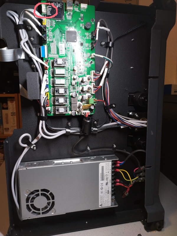
Warning: There is at least another mainboard revision 1.0.4, which may be incompatible. I have a revision 1.0.5 mainboard and obviously, it worked.
If you have comments or request, please go to https://www.reddit.com/r/FlashForge/comments/1bbkg8q/klipper_on_flashforge_creator_pro2/.I do not get notifications from the comment section as wiki.js lacks that feature.
Got shadowbanned by reddit, so write me an email.
¶ Klipper
¶ Updates
- 2024-11-10 Updated firmware and merged klipper mainline
- 2024-04-20 Updated code, config & documentation. End of development for now (Version "1.0.0")
¶ Status
¶ Works
Short: Almost everything
¶ In Progress
- Getting basic version into mainline Klipper
¶ Caveats
- Flashing only possible with ST-LinkV2 (clone), haven't managed to enter DFU mode
even with with Klipper already flashedbefore klipper was flashed. - When using copy/mirror mode, both filaments should use the same parameters (temperature, cooling), probably just a Cura issue.
¶ Not implemented / Tested
- Beeper
- Display
- Internal connection via UART
- Other hardware revisions
¶ Installation
There are two types of configurations
- Basic configuration: This is the one I try to get into klipper mainline. Most things work, but some parts are omited which need to much code. You can only use 198mm x 148mm x 150mm of the print bed.
- Advanced configuration: Here are more features and you can configure the offset of the left extruder. You can also use the full size of the print bed, witha small caveat. I think this variant is less welcomed in klipper, but I use this of course.
I assume you have a system with Klipper installed and know how to run Linux commands. I use MainsailOS on a Raspberry Pi. And you need a STLinkV2 (5€ clone is fine) device .
¶ Advanced Configuration: Extended Print Bed
The advanced configuration uses an extended print bed by default. Technically nothing prevents you from setting the same value in the base configuration. And vice versa, the “safe area" of the basic configuration is also contained in the advanced configuration, but commented out, feel free to switch to them, it's just not the default.
What is the extended print bed? The print bed is roughly 231mm x 154mm, but Flashprint only allows 200mm x 148mm. Each extruder has a small area where it cannot go. 15mm for the right extruder and 18mm for the left extruder. In Copy/Mirror mode you can safely use this extend area and in IDEX mode if your print object allows it. A bad picture:
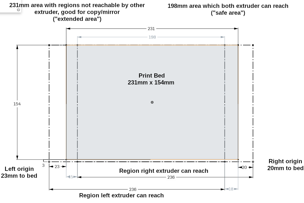
Technically you can also print between the park positions and the print bed if you like to, there is commented out configuration in the advanced configuration. Just in case if you have put a larger pei sheet on it, or like rat nests in your printer.
¶ Instructions
If there is only one cell in a row, the instructions are the same for both variants.
| Basic Configuration | Advanced Configuration |
|---|---|
|
|
git checkout ffcp2_basic |
git checkout ffcp2 |
|
|
|
|
|
Recommended instead:
|
|
|
|
Right Extuder Z-Axis Calibration If you used a shim for height compensation for a different prind bed surface (glass, PEI, etc), remove it. You do not need it.
|
|
| Not implemented |
Offset calibration left extruder If you can calibrate and set the offsets in your slicer, you should do it there, but you can do it at the Klipper level. The offsets work only for the IDEX mode, for Copy/Mirror modes obviously not. I assume you calibrated the right extruder. In the printer.cfg is the following macro with three important settings: Here you set the values relative to the right nozzle at the same point, e.g. center. In this case my left nozzle is on the x axis exact, 0.5mm more to the front than the right nozzle and 0.115mm higher (the bed moves down!) than the right nozzle. I did this with help of a soft duct tape I put on the print bed. Move the right nozzle over it. Move the nozzle down, so it leaves a spot in the duct tape. Raise the print head, switch to the other (which will home the previous print head), move to the same coordinates, lower the nozzle, raise & move it away and measure the offset of both spots. if there is only one, you are done. Z offset:
|
¶ Cura Setup
| Basic Configuration | Advanced Cofinguration |
|---|---|
|
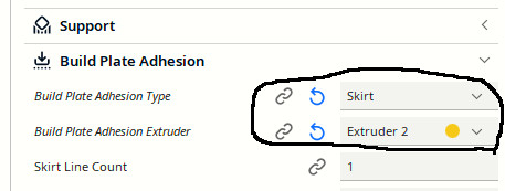
If you want to use the Copy/Mirror mode, I highly recommend installing the Cura IDEX plugin from
|
|
The end code is just 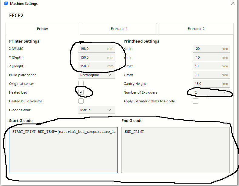
|
|
|
The dimensions are:
|
The dimensions are dependent on what you set in the Klipper config files as limits. My recommendations are:
|
|
If you are not using the Cura IDEX plugin, you have to change the start code for the copy/mirror modes. Replace the placeholder {idex_mode} with:
You probably also have to adjust the print bed size to half y, but I haven't tested this manually. The IDEX plugin is really highly recommended. |
|
|
In IDEX mode, when using left or both extruders, take care of the following:
 |
|
|
Notes:
|
|
| No problem |
Warning: When using the extended print bed size, be careful not to send the extruders in IDEX mode outside of the reachable area. The print will simply fail on the first move into this direction. With my settings:
In Copy/Mirror mode this is not an issue as every extruder stays on his half. |
¶ Hardware
¶ Components
| Part | Model | Description | Links | Replacements | Pictures |
|---|---|---|---|---|---|
| Display | INANBO-T35C-V16-A2 | http://www.inanbo.com/products.php?type=tft (broken) | |||
| Display Touchscreen Controller | XPT2046 | https://grobotronics.com/images/datasheets/xpt2046-datasheet.pdf | |||
| Extruder Fan | Peerless Motors DF4010B24 | 24V 0.08A | https://www.dxymotors.com/zhiliufengshan/25-51.html | ||
| Extruder Stepper Driver | Hangzhou Ruimeng Tech MS35775 | TMC2208 Clone, 16 Microsteps | https://jlcpcb.com/partdetail/Hangzhou_RuimengTech-MS35775/C1509055 | ||
| Extruder Stepper Motor | HEM-17D4002-56 | ||||
| Mainboard Fan | Peerless Motors DF4020B24 | PN EF80N | https://www.dxymotors.com/zhiliufengshan/25-52.html | ||
| Microcontroller | STM32F407ZG | https://www.st.com/en/microcontrollers-microprocessors/stm32f407-417.html | |||
| Part Fan | HXH HBB3505UG | 5V 0.25A | https://www.hxhfan.com/show/595.html?lang=en | ||
| PSU Fan | Protechnic MGA6012HB-O10 |
60x60x10 12V 0.17A 15.97CFM 33.5dB(A) |
http://protechnic.com.tw/dc-fan-60x60x10mm/ | ||
| Stepper Driver | Allegro MicroSystems 4988ET | 16 Microsteps | https://www.allegromicro.com/-/media/files/datasheets/a4988-datasheet.pdf | ||
| Stepper Motors |
¶ MCU Pins
| Pin # | Name | Interesting | Description |
| 1 | PE2 | No | XB Line Regulator Manual Reset |
| 2 | PE3 | No | XB Line Regulator Reset Output |
| 3 | PE4 | Yes | XB Driver En |
| 4 | PE5 | Yes | XB Driver Step |
| 5 | PE6 | Yes | XB Driver Dir |
| 6 | VBAT | No | ??? Unconnected |
| 7 | PC13 | No | ??? Unconnected |
| 8 | PC14 | No | ??? Unpopulated |
| 9 | PC15 | No | ??? Unpopulated |
| 10 | PF0 | No | Z1 Driver Line Regulator Manual Reset |
| 11 | PF1 | No | Z1 Driver Line Regulator Reset Output |
| 12 | PF2 | Yes | Z1 Driver En |
| 13 | PF3 | Yes | Z1 Driver Step |
| 14 | PF4 | Yes | Z1 Driver Dir |
| 15 | PF5 | No | Y Line Regulator Manual Reset |
| 16 | VSS | No | GND |
| 17 | VDD | No | +3.3V |
| 18 | PF6 | No | Y Line Reguator Reset Output |
| 19 | PF7 | Yes | Y Driver En |
| 20 | PF8 | Yes | Y Driver Step |
| 21 | PF9 | Yes | Y Driver Dir |
| 22 | PF10 | Yes | XL Line Regulator Manual Reset |
| 23 | PH0 | No | Osciilator |
| 24 | PH1 | No | Osciilator |
| 25 | NRST | Yes | Reset |
| 26 | PC0 | Yes | XL Line Regulator Reset Output |
| 27 | PC1 | Yes | XL Driver En |
| 28 | PC2 | Yes | XL Driver Step |
| 29 | PC3 | Yes | XL Driver Dir |
| 30 | VDD | No | +3.3V |
| 31 | VSSA | No | GND |
| 32 | VREF+ | No | +3.3V |
| 33 | VDDA | No | +3.3V |
| 34 | PA0 | Yes | Mainboard Fan |
| 35 | PA1 | Yes | MOSFET Heater Bed |
| 36 | PA2 | Yes | MOSFET Extruder L Heater |
| 37 | PA3 | Yes | MOSFET Extruder R Heater |
| 38 | VSS | No | GND |
| 39 | VDD | No | +3.3V |
| 40 | PA4 | No | Flash CS |
| 41 | PA5 | No | Flash CLK |
| 42 | PA6 | No | Flash DO |
| 43 | PA7 | No | Flash DI |
| 44 | PC4 | Yes | NTC Heat Bed |
| 45 | PC5 | No | ??? Unconnected |
| 46 | PB0 | Yes | Part Fan L |
| 47 | PB1 | Yes | Extruder L Fan |
| 48 | PB2 | No | ??? Unconnected |
| 49 | PF11 | No | Flash Hold/Reset |
| 50 | PF12 | Yes | Extruder ADS1118 SPI CS |
| 51 | VSS | No | GND |
| 52 | VDD | No | +3.3V |
| 53 | PF13 | Yes | Part Fan R |
| 54 | PF14 | Yes | Extruder R Fan |
| 55 | PF15 | No | ??? Unconnected |
| 56 | PG0 | Yes | Y min Stop |
| 57 | PG1 | Yes | Z Min Stop |
| 58 | PE7 | No | Display ? |
| 59 | PE8 | No | Display ? |
| 60 | PE9 | No | Display ? |
| 61 | VSS | No | GND |
| 62 | VDD | No | +3.3V |
| 63 | PE10 | No | Display ? |
| 64 | PE11 | No | Display ? |
| 65 | PE12 | No | Display ? |
| 66 | PE13 | No | Display ? |
| 67 | PE14 | No | Display ? |
| 68 | PE15 | No | Display ? |
| 69 | PB10 | No | ??? Unconnected |
| 70 | PB11 | No | Beeper |
| 71 | VCAP_1 | No | GND |
| 72 | VDD | No | +3.3V |
| 73 | PB12 | No | SDCard CS |
| 74 | PB13 | No | SDCard CLK |
| 75 | PB14 | No | SDCard MISO |
| 76 | PB15 | No | SDCard MOSI |
| 77 | PD8 | No | Display ? |
| 78 | PD9 | No | Display ? |
| 79 | PD10 | No | Display ? |
| 80 | PD11 | No | Display ? |
| 81 | PD12 | No | SDCard CD |
| 82 | PD13 | No | ??? Unconnected |
| 83 | VSS | No | GND |
| 84 | VDD | No | +3.3V |
| 85 | PD14 | No | Display |
| 86 | PD15 | No | Display |
| 87 | PG2 | No | ??? Unconnected |
| 88 | PG3 | No | EEPROM SDA |
| 89 | PG4 | No | EEPROM SCL |
| 90 | PG5 | Yes | LED B |
| 91 | PG6 | Yes | LED G |
| 92 | PG7 | Yes | LED R |
| 93 | PG8 | No | ??? Unconnected |
| 94 | VSS | No | +3.3V |
| 95 | VDD | No | GND |
| 96 | PC6 | Yes | Right X Stop |
| 97 | PC7 | Yes | Left X Stop |
| 98 | PC8 | No | ??? Unconnected |
| 99 | PC9 | No | Display |
| 100 | PA8 | No | USB SOF |
| 101 | PA9 | Yes | USART1_TX |
| 102 | PA10 | Yes | USART1_RX |
| 103 | PA11 | Yes | USB FS DM |
| 104 | PA12 | Yes | USB FS DP |
| 105 | PA13 | Yes | SWD-DIO |
| 106 | VCAP_2 | No | GND |
| 107 | VSS | No | GND |
| 108 | VDD | No | +3.3V |
| 109 | PA14 | Yes | SWD-CLK |
| 110 | PA15 | No | Display |
| 111 | PC10 | Yes | Extruder ADS1118 SPI CLK / Display |
| 112 | PC11 | Yes | Extruder ADS1118 SPI MISO / Display |
| 113 | PC12 | Yes | Extruder ADS1118 SPI MOSI / Display |
| 114 | PD0 | No | Display ? |
| 115 | PD1 | No | Display ? |
| 116 | PD2 | No | |
| 117 | PD3 | No | |
| 118 | PD4 | No | Display |
| 119 | PD5 | No | Display |
| 120 | VSS | No | GND |
| 121 | VDD | No | +3.3V |
| 122 | PD6 | No | |
| 123 | PD7 | No | Display |
| 124 | PG9 | No | |
| 125 | PG10 | No | Display |
| 126 | PG11 | No | Display |
| 127 | PG12 | No | Display |
| 128 | PG13 | No | Display |
| 129 | PG14 | No | Display |
| 130 | VSS | No | GND |
| 131 | VDD | No | +3.3V |
| 132 | PG15 | Yes | XR Line Regulator Manual Reset |
| 133 | PB3 | Yes | XR Line Regulalor Reset Output |
| 134 | PB4 | Yes | XR Driver Enable |
| 135 | PB5 | Yes | XR Driver Step |
| 136 | PB6 | Yes | XR Driver Dir |
| 137 | PB7 | Yes | XA Line Regular Manual Reset |
| 138 | BOOT0 | No | Boot0 |
| 139 | PB8 | Yes | XA Line Regulator Reset Output |
| 140 | PB9 | Yes | XA Driver Enable |
| 141 | PE0 | Yes | XA Driver Step |
| 142 | PE1 | Yes | XA Driver Dir |
| 143 | PDR_ON | No | +3.3V |
| 144 | VDD | No | +3.3V |
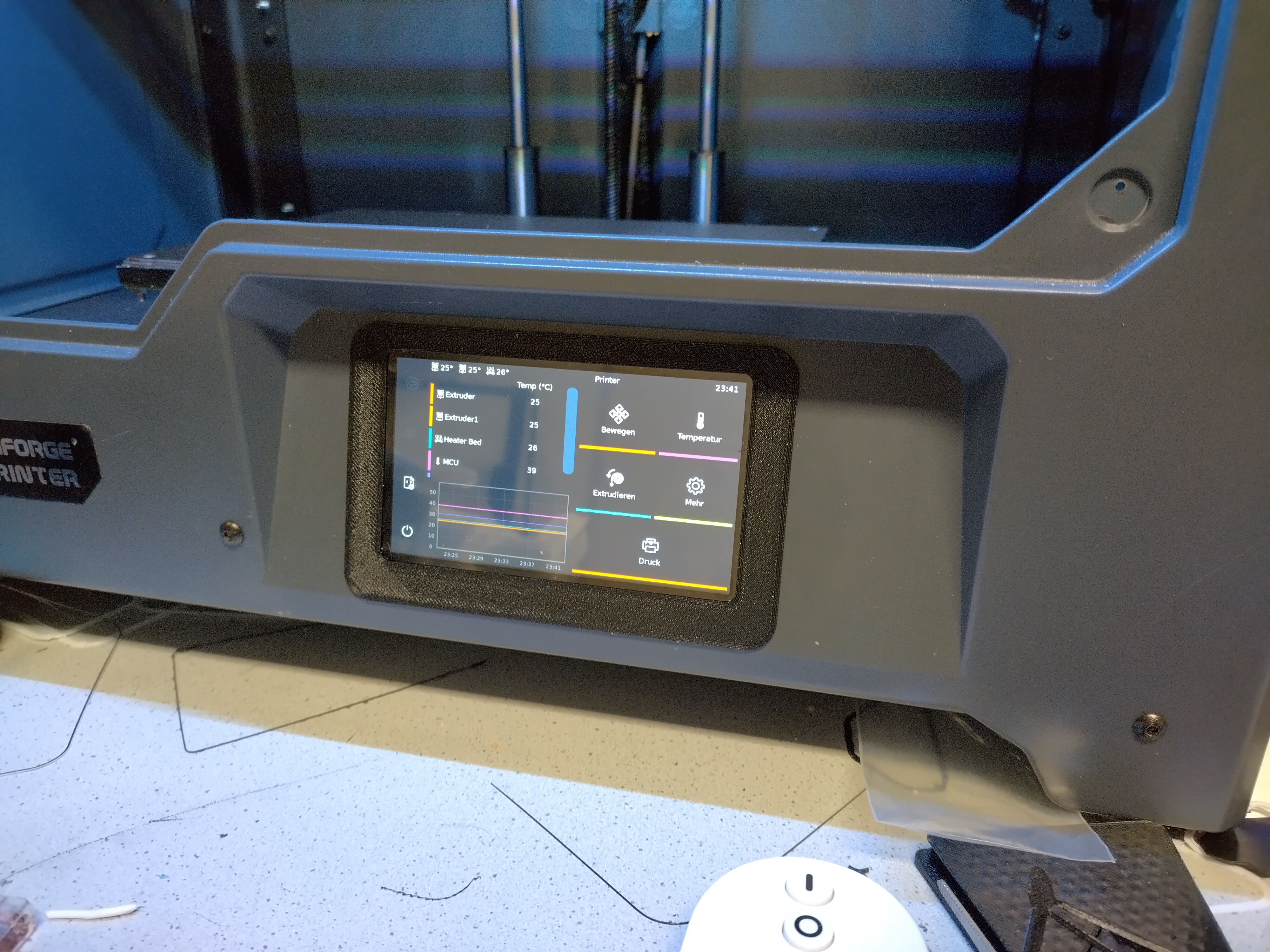
¶ Inaccurate Extruder Temperature Readings
The extruders use thermocouples for reading the temperature. The thermocouple measures the temperature at its tip which is in the extruder heat block. But it needs a reference point outside of the extruder, the cold junction, which is located in the cable going to the extruder top. The thermocouple generates a voltage dependent on the temperature difference between these two points, the print chamber and the extruder. And for an absolute value, you need the absolute temperature of this cold junction in the print chamber. But there is no such sensor in the print chamber near the extruder.
So, the reference temperature is measured in the ADC chip on the mainboard in the compartment below the print chamber. But this has its own temperature region and can be hotter or colder than the print chamber. And there will always be an error of roughly the temperature difference between these two regions which can easily be around 20°C and change during use.
Maybe FlashForge has some magical code in their firmware correcting this issue, but I doubt it.
¶ Modifications
Coming Soon.
- Display case for KlipperScreen (replaces the original display), DSI to Raspi
- Camera mount, CSI to Raspi (need to correct angles and position)
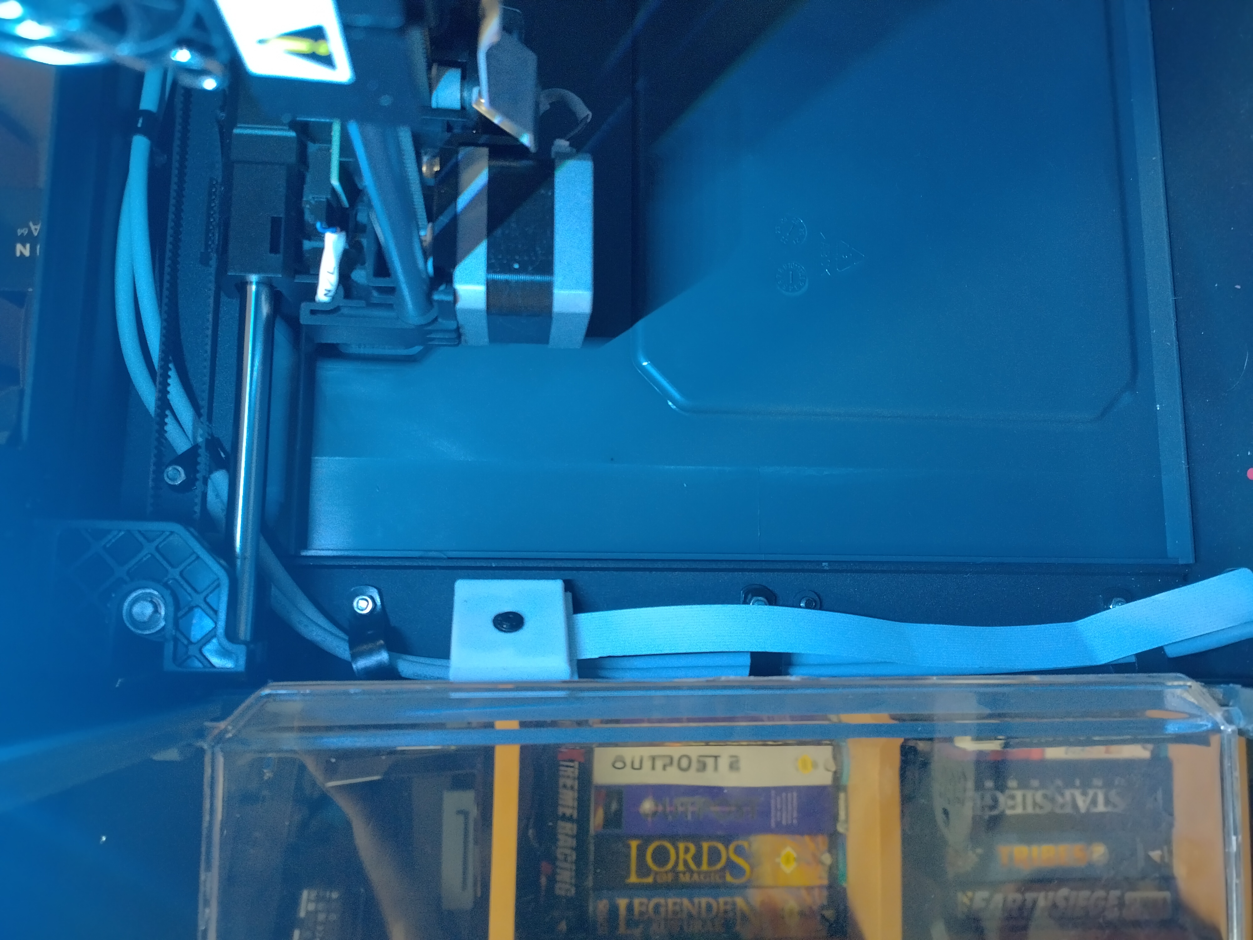
- Internal Raspi mount between mainboard and PSU
¶ Software
¶ STM32 Flashing Tools
Under Windows, the ST-Link Utility works more reliable as the STM32CubeProgrammer. Download: https://www.st.com/en/development-tools/stsw-link004.html
In Linux, I had more success with the stlink-gui. Get it from your distro repository. Github: https://github.com/stlink-org/stlink
¶ Links
https://www.reddit.com/r/FlashForge/comments/1bbkg8q/klipper_on_flashforge_creator_pro2/
https://www.reddit.com/r/FlashForge/comments/145u0p9/another_poor_soul_trying_to_klipperise_his/
https://www.st.com/en/development-tools/stsw-link004.html
Cura Dual-Extruder Fun: https://community.ultimaker.com/topic/37784-cura-generating-gcodes-before-start-gcode/