Disclaimer. This is description is how I did it with my J1 → J1s upgraded model. You might have a different revision or variant. I may be able help you with your variant or not. Depends on how I can simulate these differences.
If you need support, please go to https://www.reddit.com/r/KlipperOnJ1/
The installation bundle can be downloaded from https://github.com/eazrael/klipper4j1/releases
¶ Requirements
Hardware
- USB-A to USB-A cable (from HTC Vive, USB hubs, etc.), USB 2.0 is sufficient
- Linux computer with ~20GB free space for backup and the storage image, a RasPi with USB Stick or SD-card will work
¶ Installation
¶ Overview
- Install necessary tools on a Linux computer (any Raspberry Pi will do).
- Disassemble the lower part of the printer, to get access to MCU and Display PCB.
- Connect the display to linux computer via the J1 front USB port (USB-A to USB-A), boot into EDL-mode
- Create a backup of your display's storage, create a new image, and flash it to the display
- Setup display
- Flash microcontroller
- Calibrate Heaters, offset, etc
- Setup printer in OrcaSlicer
Of course you are free to do the changes in any order.
¶ Linux preparation
Please note that lines starting with # indicates a root shell and $ is used for a normal user shell.
Make sure the following base software is installed (it is normally..):
- dd
- sfdisk
- bash
- tar
- xf
- losetup
- python3
Install edl. Follow the instructions in the README of the github repository.
This is how I did this on Ubuntu & Armbian:
$ git clone https://github.com/bkerler/edl
$ git submodule update --init --recursive
$ cd edl
$ python3 -m venv "$(pwd)"
$ source bin/activate
$ pip3 install -r requirements.txtAFAIR I did not need to install any drivers or rebuild the initrd.
Download the latest installation_bundle from https://github.com/eazrael/klipper4j1/releases to a convenient directory. and untar it,
$ mkdir work
$ cd
$ tar -xvf installation_bundle.tar.xz
$ cd installation_bundle
$ ls -al
create_image.sh
idex_calibrate.3mf
lk2nd.img
mainsailos.img
README.md
Snapmaker J1 (0.4 nozzle) - Klipperized.orca_printer
¶ File Contents
| create_image.sh | Script to create a new flash image |
| lk2nd.img | Bootloader |
| mainsailos.img | OS Image |
| Snapmaker J1 (0.4 nozzle) - Klipperized.orca_printer | Printer definition for OrcaSlicer |
| idex_calibrate.3mf | Model for calibrating second extruder XY offsets |
¶ Disassembly
You can follow the instructions in the Snapmaker Wiki: https://wiki.snapmaker.com/en/snapmaker_j1/troubleshooting/touchscreen_replacement_guide
First remove the the floor plate of the print chamber by removing all the screws visble from above. AFAIR there is one hidden beneath a sticker. You should see the mainboard and the PSU.
Remove the front bracket and open the display case by removing two or four screws, one beneath the QC sticker. You should be able to remove the back cover from the front display and see a black bracket on the back of the display. Be careful with the WiFi antenna.
There should be no need to the remove the front cover of the display, it's glued to the display, so try to avoid removing it. Please also do not disconnect the flat flexible cable (FFC), mine broke while doing so.
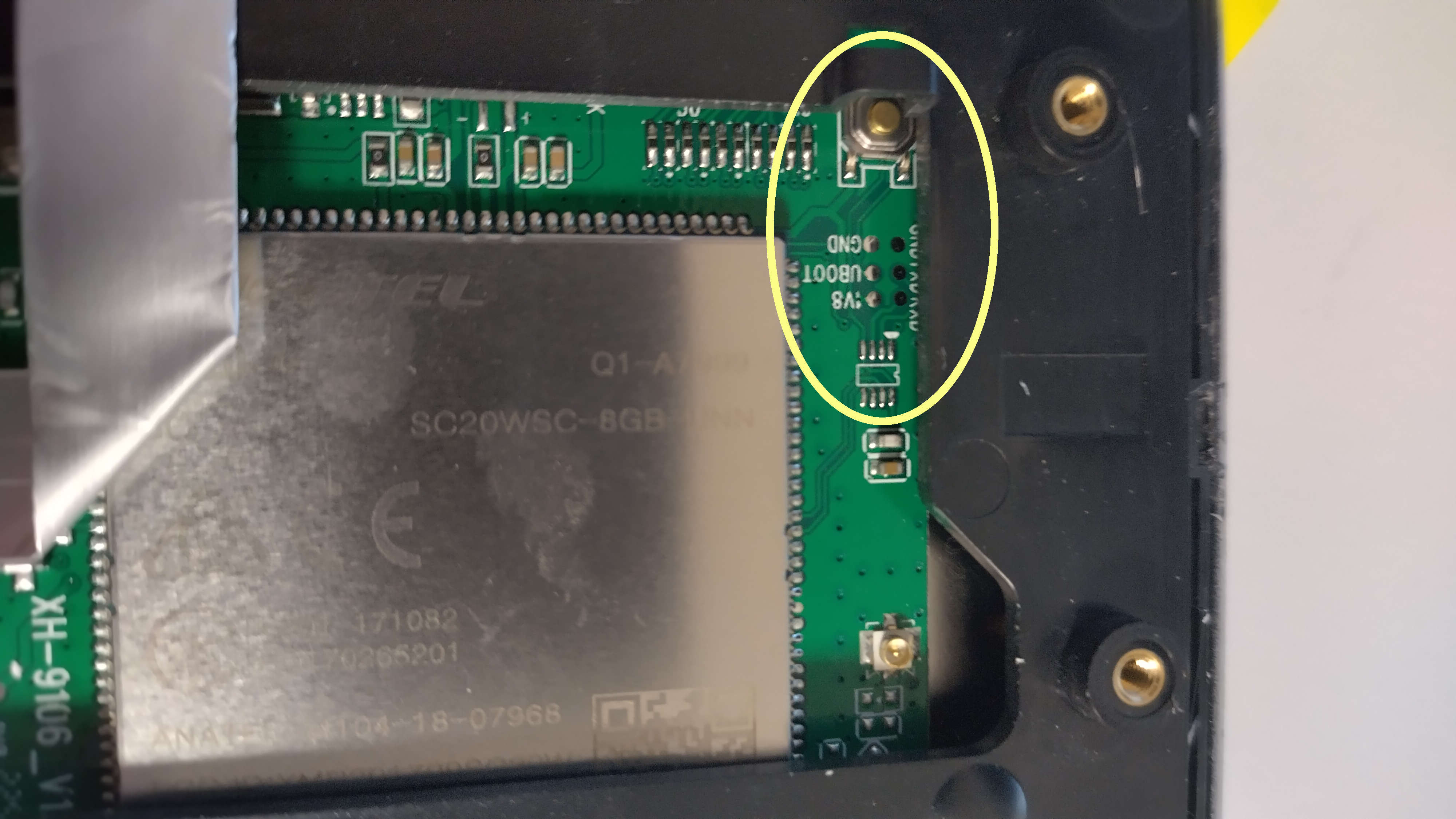
You need to be able to press the button in the upper right corner of the following picture.
There is a board version with different layout and this button missing, but connecting the pads labeled 1V8 and UBOOT/BOOT should do the same.
¶ Install display image
The J1 should be powered off. Plug one end of the USB-A to USB-A cable in your Linux computer. Keep the EDL button pressed (or short/connect the 1V8 and BOOT/UBOOT pads) and plug the USB-A into the front USB of the J1. This will power on display, mainboard and possibly the chamber LED (total power draw ~1.5 Watt), wait a 2-3 seconds, the display will stay black. You can release the button.
On the Linux system, check with lsusb the devices found
# lsusb
Bus 004 Device 001: ID 1d6b:0003 Linux Foundation 3.0 root hub
Bus 003 Device 005: ID 05c6:9008 Qualcomm, Inc. Gobi Wireless Modem (QDL mode)
Bus 003 Device 001: ID 1d6b:0002 Linux Foundation 2.0 root hub
Bus 002 Device 002: ID 090c:1000 Silicon Motion, Inc. - Taiwan (formerly Feiya Technology Corp.) Flash Drive
Bus 002 Device 001: ID 1d6b:0003 Linux Foundation 3.0 root hub
Bus 001 Device 001: ID 1d6b:0002 Linux Foundation 2.0 root hubWhen you see the Gobi Wireless Modem, you booted into the EDL mode and can read and write the internal flash. If it does not work then disconnect and try again. The LED in the J1 might be turned on & flicker, especially during transfers, but it's harmless.
First backup the full flash of the display. You need it to create the new Klipper image and you can revert later to the original snapmaker firmware if you need to.
# cd edl
# source bin/activate
(venv) # ./edl rf backup-20260228.img
Qualcomm Sahara / Firehose Client V3.62 (c) B.Kerler 2018-2025.
main - Trying with no loader given ...
main - Waiting for the device
main - Device detected :)
main - Mode detected: firehose
Dumping flash with sector count 15269888 as backup-20260228.img.
Progress: ....
Progress: |██████████| 100.0% Read (Sector 0xE90000 of 0xE90000, ) 22.20 MB/s
Dumped flash with sector count 15269888 as backup-20260228.img.This will download the flash memory from the display computer and store it in a file named backup-20260228.imgfeel free to use a different file name. Keep this file for restoring the Android system later if you wish to do so.
¶ Create new flash image
This step will create a new image from your backup. This is necessary as firmware blobs and other binareies are required which I cannot redistribute, so they are taken from your image. As this requires mounting the filesystems, root is required.
Copy the backup image you created to the installation directory. Then run the create_image.sh script which will create a new image. You need roughly 20GiB of disk space for this, 2x 8GiB images and ~4-5GiB for the MainsailOS Image.
$ cd installation_bundle
$ mv ../edl/backup-20260228.img .
$ sudo bash create_image.sh \
	backup-20260228.img \
	mainsailos.img \
	lk2nd.img \
	snapmakerj1_klipper.img

....
New image snapmakerj1_klipper.img created. Check output for errorsIf unfamiliar with Linux. the 5 lines are one command, you enter them line by line, or omit the back slahes and put in one line.
Break down of the files involved:
backup-20260228.imhg
| backup-20260228.img | Image you extracted from the printer, keep it safe |
| mainsailos.img | Mainsail OS Image in the installation bundle |
| lk2nd.img | Bootloader from the installation bundle |
| snapmakerj1_klipper.img | Generated image for flashing into the printer |
¶ Flashing the the new Image
Copy the generated Image to the edl directory or use the full path to the edl program. Remember to source activate before if it is not activated anymore. Run the edl and flash it:
# source bin/activate
(venv) # ./edl wf snapmakerj1_klipper.img
Qualcomm Sahara / Firehose Client V3.62 (c) B.Kerler 2018-2025.
main - Trying with no loader given ...
main - Waiting for the device
main - Device detected :)
main - Mode detected: firehose
firehose
firehose - [LIB]: Sector size in XML 4096 does not match disk sector size 512
modules
modules - [LIB]: 'Logger' object has no attribute 'loglevel'
Progress: |██████████| 100.0% Write (Sector 0xE8E800 of 0xE90000, ) 27.48 MB/s
Progress: |██████████| 100.0% Write (Sector 0xE8F000 of 0xE90000, ) 27.46 MB/s
Progress: |██████████| 100.0% Write (Sector 0xE8F800 of 0xE90000, ) 27.50 MB/s
Progress: |██████████| 100.0% Write (Sector 0xE90000 of 0xE90000, ) 27.28 MB/s
Wrote snapmakerj1_klipper.img to sector 0.You can use the same command ot flash your backup into
Disconnect the USB cable and power on the printer. You should see Armbian booting and after some time you should see Klipperscreen. Please note that the display may be dark for a couple of seconds or you may see the Linux termonal for some seconds. Just wait.
KlipperScreen will say that it cannot connected to the MCU, but the network configuration screen should be accessible.
¶ Display Setup
In KlipperScreen you can setup the WiFi.
If you prefer wired LAN, just plugin a USB network adapter into the front port of the J1. You can also use a USB hub (e.g. for LAN adapter, STLinkV2, USB thumbdrive, etc..). In a DHCP enabled network, it should come up automatically, you can see the IP address in Klipperscreen if needed. Hostname might be snapmakjer1.
You can login with SSH, user is “pi” and password “armbian” (may change in the future). It's an armbian/debian based system, so feel free to install what you need. Sudo is set up, use armbian as password.
Mainsail is set up as Web UI, just navigate with your browser there.
¶ Flash the microcontroller
This is is easier now. My recommendation is to shutdown Klipper before doing any flash. I prefer to shutdown Klipper with the stop klipper in the Web UI.
Login to the OS vis ssh and navigate to the klipper directory. For the initial flash use the command make j1flash-initial:
$ cd ~/klipper
$ make j1flash-initial
  Flashing out/klipper.bin to  from klipper via SACP
...
  Flashing complete, restart klipper
The flashing may fail randomly due to some internal timeouts. In case of errors, wait 30 seconds and try again.
When reflashing after a successful klipper flash, use the command make j1flash instead. The only difference is that it that it sends klipper into the bootloader for flashing.
Important: When during powerup the chamber LED pulses, the bootloader awaits flashing. Run make j1flash-initial in this case, but the other command will also work albeit it takes takes longer.
Start the klipper service again. It should connect to the MCU.
¶ Setup OrcaSlicer
Important: The macros in Klipper are not compatible with OrcaSlicer 3.2.x. There are breaking changes.
Never did that before, so not much experience with that.
The installation package contains an OrcaSlicer definition file.
- In OrcaSlicer add a standard Snapmaker J1 with a 0.4mm nozzle.
- Go to File Menu → Import Configs and choose the Printer definition file
- In the printer drop down should be a "Snapmaker J1 0.4mm - Klipperized
- You can delete the standard Snapmaker J1 profile if you like
- Connect the printer in Orcaslicer.
Notes:
- The option “Prime all extruders” will cancel the print.
- The prime tower is a big too huge for my taste.
- Left extruder is the first extruder.
¶ Calibrate Printer
Calibrate the heaters with the command PID_CALIBRATE.
To calibrate the left extruder (the good ol' way):
- Make sure both nozzles are clean with no filament residue below the nozzles.
- Heat up the print bed to the usual printing temperature.
- Home all axes.
- Move the left extruder to the center of the print bed, coordinates (x= 175, y=100)
- Raise/Lower the print bed to ~5mm.
- Put a piece of paper under the nozzle
- Slowly close the distance between the print bed und nozzle until the paper moves with a bit of friction. In Mainsail you can make finer movements by entering position values directly. Take the final z-position. Edit the printer.cfg, and subtract your final z value (which may be negative) from the position_endstop and position_values. Save, restart Klipper and verifiy the position
- Position the extruder nozzle over the leveling knobs, put a piece of paper over between print bed and nozzle and adjust the the distance until the piece of paper moves with a slight friction.
- Switch to the right extruder (command: T1) und move it to the center (x=175, y=100). Loose the screws keeping the hotend in place. Raise the print bed carefully to position 0. Use the wheel on the extruder to lower or raise the nozzle. Measure with a paper sheet the height as with the first nozzle. Tighten the screws afterwards.
¶ XY-Offset Second Extruder
The automated XY-Offset calibration is not implemented, So this is a manual step.
Use the model from download package (TODO). It's an already merged version of XY calibration by “LMaker” at https://www.printables.com/model/129617-offset-xy-dual-extruder-idex-calibration, there is also an explanation how to read the results.
In short
- Print the lower part of the model with the left extruder and the upper part with the right extruder.
- On the printed model you will see two axes with bars.
- Find on each axis the bar which is perfectly aligned, either on the plus side or minus side. Multiply the 0-based index of the matching bar with 0.1 to get the offset, e.g. if the third negative har matches, it (3 -1) *-0.1 = -0.2
- Edit the printer.cfg file, you can do this from the Web UI.
- Find the lines
variable_right_nozzle_adjust_x: 0andvariable_right_nozzle_adjust_y: 0. Subtract the offset you calculated from the current value. - Save, Restart Klipper, print again and the first bars on each axis should be aligned.
Finer calibration: (TODO)
¶ Other Calibration
Do the calibrations provided by OrcaSlicer in your preferred order.
¶ Building the disk images
You need a linux machine, docker, bash and the gcc-arm toolchain (mainly for lk2nd).
The images are build from the following Github repositories and branches:
| Repository | Branch | What |
|---|---|---|
| https://github.com/eazrael/klipper4j1 | master | Build script build/build.sh |
| https://github.com/eazrael/lk2nd | snapmakerj1 | Bootloader |
| https://github.com/eazrael/armbian-build | snapmakerj1 | Armbian base image for MainsailOS |
| https://github.com/eazrael/klipper | snapmakerj1 | Klipper for the Snapmaker J1 |
| https://github.com/eazrael/MainsailOS | snapmakerj1 | MainsailOS, needs Armbian image + Klipper |
To build everything
- Clone the klipper4j1 repository
- Create an empty build directory, switch to it
- Call build.sh from your empty directory
- You will find the mainsailos.img and lk2nd.img in your build repository
Example:
$ git clone git@github.com:eazrael/klipper4j1.git
$ cd klipper4j1
$ mkdir mybuild
$ cd mybuild
$ bash ../build/build.sh
... wait ...Sometimes the Armbian or MainsailOS build fails with an error that no free loop device can be found. Just try again.
Depending on your system setup, root may be required, so you may need to call it with sudo or as root.
¶ Further Development
Not by me.
¶ Use firmware partitions
The firmware blobs for WiFi are on the partitions modem & persist. Instead of extracting them in create_image.sh, just mount the partitions and symlink the required files where the OSS drivers need them.
¶ Use installation APK instead of disassembling device
Someone managed to install new APKs on the android (https://forum.snapmaker.com/t/setup-of-my-j1s-android-software-and-tweaks/38638). There are /system/xbin/su and /system/bin/dd available on the printer. Package the lk2nd-fastboot.img into the APK and write it with su && dd into the boot partition. The system should boot into fastboot-capable lk2nd. It will wait there for 5 min and the command fastboot oem reboot-edl will boot into EDL for flashing as described above.